DIP Switch - Spider IoT (HW ≥3.5)
The Spider IoT v3.5+ has a 4-position DIP switch. Each switch connects or disconnects a connector terminal from a microcontroller pin: none of them enables or disables features in software.
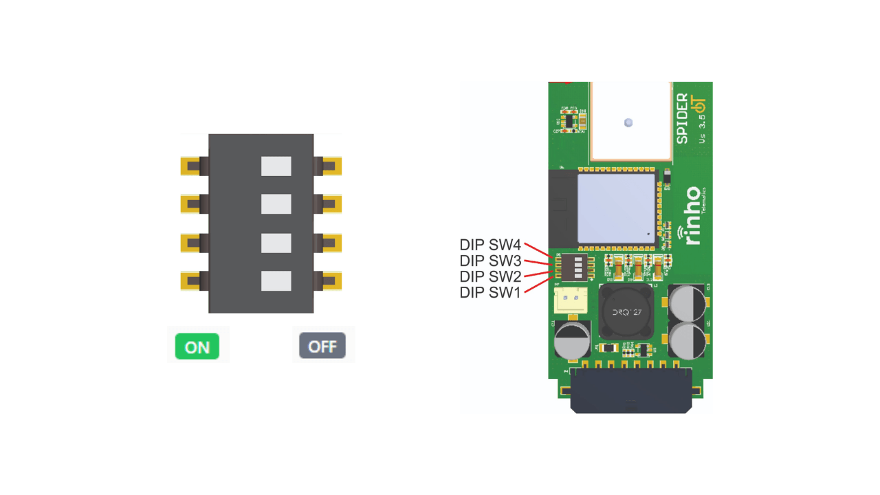
What each switch does
| Switch | ON | OFF |
|---|---|---|
| DIP 1 | IN03/CANL terminal connected to the IN03 / 1-Wire pin | IN03 disconnected (terminal left as CAN-L only) |
| DIP 2 | IN01/XP01 terminal connected to the IN03 / 1-Wire pin | IN01/XP01 disconnected from 1-Wire |
| DIP 3 | IN01/XP01 terminal connected to the IN01 input (voltage reading) | IN01 is not read |
| DIP 4 | 120 Ω termination between CAN-H and CAN-L | No termination |
IN03 and 1-Wire are the SAME microcontroller pin. DIP 1 and DIP 2 are two paths to that single pin: DIP 1 routes it to the IN03/CANL terminal, DIP 2 to the IN01/XP01 terminal. When a 1-Wire sensor is in use, IN03 reads the bus.
Quick Reference
| DIP 1 | DIP 2 | DIP 3 | DIP 4 | Configuration |
|---|---|---|---|---|
| OFF | OFF | ON | OFF | Standard: IN01 as input, no CAN termination |
| OFF | OFF | ON | ON | Standard + CAN termination |
| OFF | ON | OFF | OFF | 1-Wire on the IN01/XP01 terminal (iButton, temperature sensor) |
| OFF | ON | OFF | ON | 1-Wire on IN01/XP01 + CAN termination |
| ON | OFF | ON | OFF | 1-Wire / IN03 on the IN03/CANL terminal — only if CAN is not wired |
Combinations to avoid
| Combination | Problem |
|---|---|
| DIP 1 + DIP 2 both ON | Shorts the IN03/CANL terminal to the IN01/XP01 terminal |
| DIP 2 + DIP 3 both ON | The input divider (100 kΩ) loads the 1-Wire bus and degrades communication |
| DIP 1 ON with CAN wired | The microcontroller pin hangs off the CAN-L differential line |
CAN bus
The DIP switch does not enable or disable CAN. The transceiver is turned on and off by firmware, through the CAN configuration commands. All DIP 4 does is add the 120 Ω termination resistor.
- Termination (DIP 4): only activate if the device sits at one end of the bus.
- CAN-L shares its terminal with IN03: if CAN is wired, leave DIP 1 OFF.
XP01 output
XP01 does not go through any DIP switch. The open-drain output is permanently connected to the IN01/XP01 terminal. If that terminal is used as an input (DIP 3) or as 1-Wire (DIP 2), XP01 must stay off: activating it pulls the terminal to ground.
Voltage levels
IN03 and 1-Wire run at 3.3 V. They only have a 3.6 V protection clamp — do not apply vehicle voltage (12 V / 24 V) to those terminals.
The pin carries a 1 kΩ pull-up to 3.3 V, so IN03 idles high and goes low when the terminal is pulled to ground.
R36 / R31 jumpers
The v3.4 jumpers are still present on versions 3.5 and higher. They set the function of the IN00 terminal on the Microfit connector.
| Jumper fitted | IN00 terminal function |
|---|---|
| R36 | IN00/XP02 enabled (standard); 3V3 EXT output disabled |
| R31 | 3V3 EXT output enabled; IN00/XP02 disabled |
Only one of the two may be fitted.
See Also
- Hardware Spider IoT v3.4 - Previous versions
- Spider IoT - Installation - Installation guide
- CAN Commands - Software configuration