CANBUS Contactless
Inductive CAN reader without electrical connection
✅ 1 Mbps ✅ 8-90V ✅ < 20g ✅ –40°C to +85°C
Description
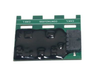
The CANBUS Contactless reads the vehicle’s CAN bus traffic without cutting or splicing any wires. The CAN-H and CAN-L wires are secured to the board with zip ties; the board picks up the signal through inductive coupling and delivers it through a CAN passthrough output to any tracker or telematics device with a CAN input.
This manual applies to any tracker brand. At the end there is a section with the specific configuration for Spider IoT and Smart IoT.
The contactless reader is read-only: it cannot write to the vehicle bus. It reads the data that the vehicle’s modules publish on their own, but it is not compatible with OBD-II: getting an OBD-II value requires writing a request on the bus. Before installing, check what data can be read.
Before you start
What you need
- A tracker or telematics device with a CAN input (CAN-H / CAN-L)
- Plastic zip ties to secure the wires to the board
- A multimeter to confirm that the wire pair is the CAN bus
- Vehicle power between 8 and 90 VDC for the module
What data can be read
Vehicle data travels over the CAN bus in two ways, and the contactless reader can only read one of them:
| Data type | How it travels | Readable with contactless? |
|---|---|---|
| Broadcast | The vehicle’s modules (engine, ABS, instrument cluster) publish it on their own, continuously | ✅ |
| Request (on demand) | It only appears when someone queries the ECU | ❌ |
| ✅ Can be read | ❌ Cannot be read |
|---|---|
| J1939 / FMS on trucks, buses and machinery: RPM, speed, fuel, consumption, temperature, engine hours | OBD-II PIDs (the tracker asks and the ECU answers) |
| Active J1939 faults (DM1), which the ECU broadcasts on its own | OBD2 faults (Mode 03) and VIN over OBD-II |
| Native bus frames on light vehicles, decoded with custom parsers | Any write to the bus: CAN immobilization, clearing faults |
What each vehicle publishes depends on the manufacturer and model: not every light vehicle broadcasts the same data on its native bus. If the application depends on OBD-II requests, use a direct connection to the bus instead of the contactless reader.
Contactless or direct connection
| Aspect | Direct connection | Contactless |
|---|---|---|
| Installation | Splice to CAN-H / CAN-L | Board secured with zip ties |
| Time | 30 to 60 minutes | 5 to 15 minutes |
| Vehicle wiring | Cut or stripped | Left intact |
| Vehicle warranty | May be affected | Untouched |
| OBD-II requests and writing | ✅ | ❌ Read-only |
| Requirement | Access to the wires | Access to the wires |
Installation
Find the native CAN bus
Look for a twisted pair of wires running to the vehicle’s modules. The usual places are:
- Behind the dashboard, in the harness going to the instrument cluster or the body control module (BCM)
- In the engine harness, near the ECU
- At the connectors of modules attached to the main bus
Avoid the OBD-II diagnostic connector. On many vehicles pins 6 and 14 sit behind a gateway, and the bus stays silent unless someone sends a request. The contactless reader sees no traffic on those wires. Look for the native bus, which transmits continuously with the engine running.
CAN pair colors change with brand, model and year: color alone is not enough, you need to confirm it with the multimeter (next step).
Confirm the pair with the multimeter
- Start the engine (or at least switch the ignition on) so the bus is active.
- Set the multimeter to VDC, 20 V range or auto-range.
- Black probe (COM) to vehicle ground; red probe to the wire under test.
| Bus state | CAN-H | CAN-L | H − L difference |
|---|---|---|---|
| Recessive (idle) | 2.5 V | 2.5 V | 0 V |
| Dominant (transmitting) | 3.5 V | 1.5 V | 2 V |
| Typical reading with activity | 2.5 to 3.5 V | 1.5 to 2.5 V | fluctuates between 0 and 2 V |
To confirm, measure the differential with the red probe on CAN-H and the black probe on CAN-L: the reading should fluctuate between 0 and 2 V.
| What you measure with the engine running | Diagnosis |
|---|---|
| One wire between 2.5 and 3.5 V and the other between 1.5 and 2.5 V | ✅ It is the CAN bus, with activity |
| Both at 0 V with the engine off | ⚠️ Normal: the bus is asleep. Start the engine |
| Both at 0 V with the engine running | ❌ Not CAN, or a bus with no traffic |
| Both at ~12 V | ❌ It is power, not CAN |
| One at 5 V and the other at 0 V | ❌ Probably a digital signal, not CAN |
Secure the pair to the board
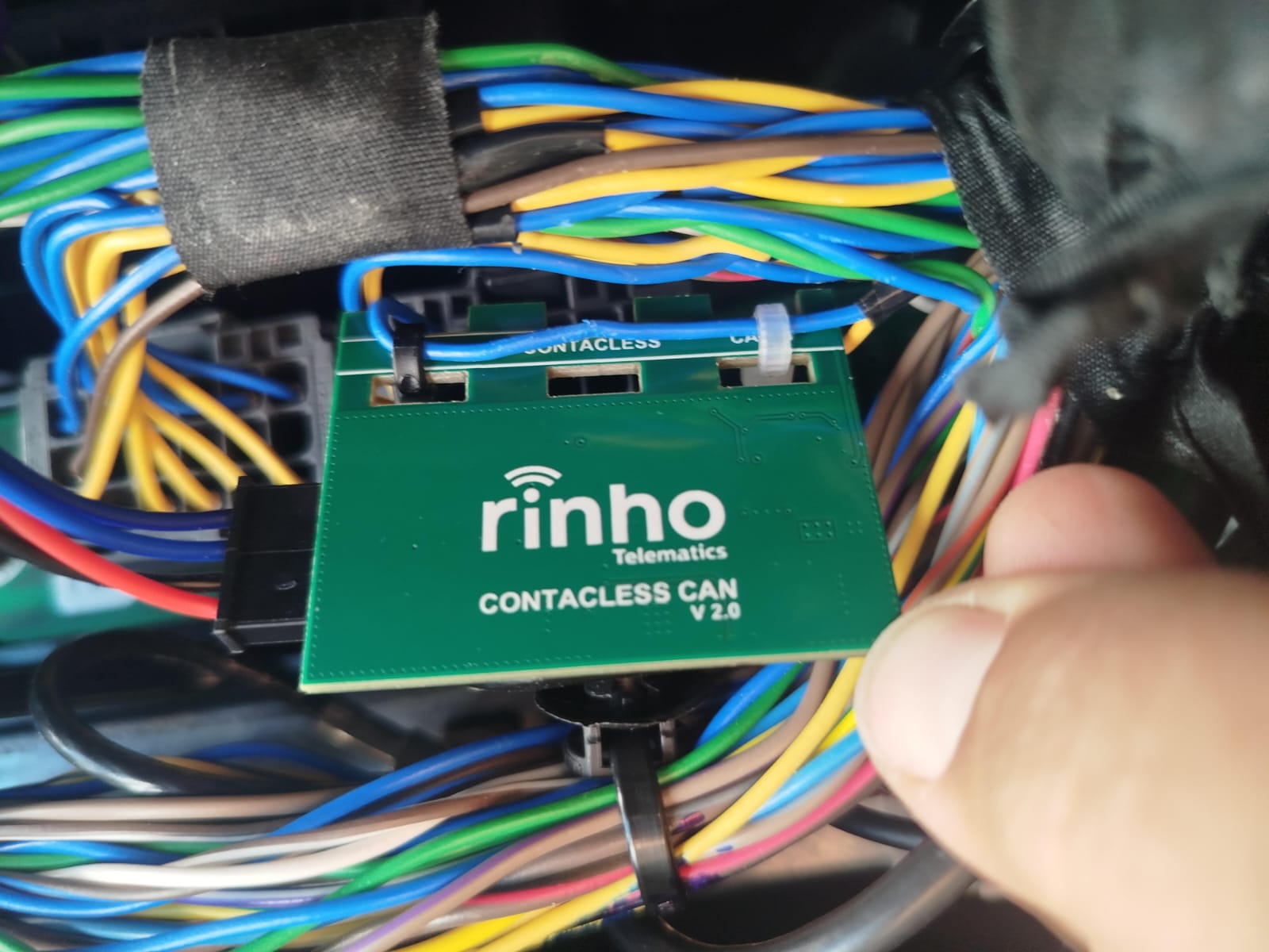
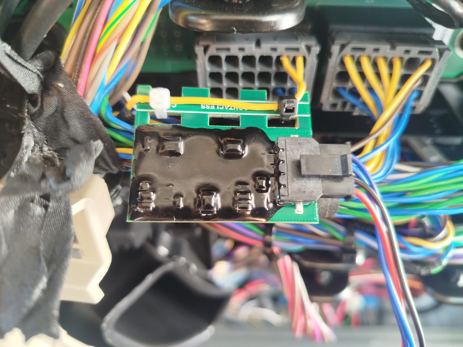
- Lay both wires of the pair (CAN-H and CAN-L) together along the top strip of the board, over the slots.
- Pass the zip ties through the slots and tighten them so the wires stay in firm contact with the board.
- Trim the zip tie ends and check that the board cannot shake loose with vibration.
There is nothing to cut, strip or splice.
Connect the module to the tracker
The module has a 4-pin connector wired as follows:
| Module wire | Function | Connects to |
|---|---|---|
| Red | Power (+) 8 to 90 VDC | Vehicle positive; it can be the same feed that powers the tracker |
| Black | Ground (GND) | Vehicle ground |
| Blue | CAN-H output | Tracker CAN-H input |
| Blue/Black | CAN-L output | Tracker CAN-L input |
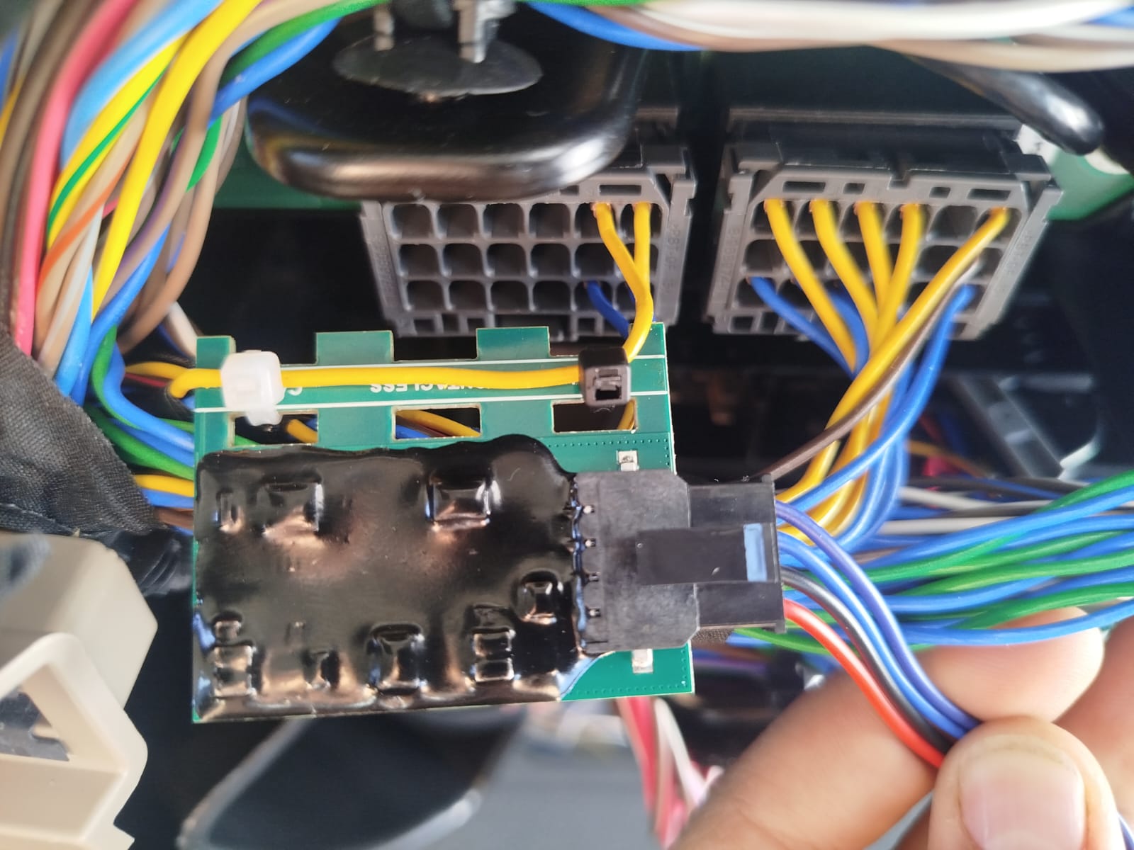
On the vehicle side the pair sits on the board regardless of polarity, but on the tracker side CAN-H and CAN-L cannot be swapped: with the output crossed, the tracker does not read any frame.
Configure the tracker
Each brand uses its own tool, but the rules are the same:
| Parameter | What to set |
|---|---|
| Bus speed | The same as the vehicle: typically 250 kbps on J1939 and 500 kbps on light vehicles. The module works from 50 kbps to 1 Mbps |
| Identifier format | 29-bit (extended) on J1939; 11-bit (standard) on most light vehicles |
| Reading mode | A mode that only listens to the bus: J1939/FMS, passive listening (listen-only / silent) or raw frames with parsers |
| Not compatible | OBD-II (PIDs, VIN and OBD2 faults): it requires writing requests on the bus |
Verify the reading
With the engine running, confirm in the tracker’s tool or on the platform that data is arriving: RPM, speed, engine temperature, fuel level or consumption, depending on what the vehicle publishes.
The module has no status LED: verification is always done from the tracker.
With Rinho trackers
Spider IoT and Smart IoT have a built-in CAN transceiver. Zero IoT has no CAN bus and is not compatible with this accessory.
Wiring
Connect the module’s CAN-H / CAN-L output to the device’s CANH and CANL wires. Colors on the tracker side change with model and version: see Spider IoT pinout and Smart IoT connectors.
Termination (DIP switch)
| Device | DIP switch |
|---|---|
| Spider IoT HW ≥3.5 | DIP 4 ON (termination). DIP 1 OFF: with the CAN wired it must not be left ON. See DIP Switch HW ≥3.5 |
| Spider IoT HW ≤3.4 | DIP 1 ON (enables CAN) and DIP 2 ON (termination). See DIP Switch HW ≤3.4 |
| Smart IoT | DIP 1 ON (enables CAN) and DIP 2 ON (termination). See Smart IoT DIP Switch |
Configuration with CXCAN
The bus is configured with the CXCAN command. With the contactless reader, use the protocols that only listen:
// Trucks, buses and machinery (J1939)
>SCXCAN1,250K,J1939,29,0,0<

// Light vehicles: native bus frames, decoded with CXECU parsers
>SCXCAN1,500K,PLAIN,11,0,0<

// Passive listening for diagnostics and bus surveys
>SCXCAN1,500K,LISTEN,11,0,0<
Do not use OBDII with the contactless reader. OBD-II needs to write requests on the bus and the contactless reader cannot write: the device gets no answer and reads no data. For the same reason, fault reading works on J1939 but not on OBD2.
The speed (250K, 500K or 1M) must match the vehicle’s. For light vehicles, the parser for each signal is defined with CXECU.
Verification
>QCXCAN<     // confirms the effective bus configuration
>QCAN00<     // J1939: RPM, fuel, consumption and temperature read from the bus
For light vehicles with custom parsers, values are queried with ECU.
Troubleshooting
| Symptom | Likely cause | What to do |
|---|---|---|
| No data at all | Tracker speed differs from the bus speed | Set the vehicle’s actual speed (250K / 500K) |
| No data at all | Board installed on the OBD-II connector or on a bus with no traffic | Measure with the multimeter and move it to the native bus |
| No data at all | Tracker configured for OBD-II | OBD-II is not compatible: switch to J1939, passive listening or raw frames |
| No data at all (Spider / Smart) | Termination DIP switch OFF | Set it ON: see Termination |
| No data at all | CAN-H and CAN-L swapped on the output to the tracker | Check the blue / blue-black wiring |
| No data at all | Module not powered | Measure voltage between red and black: it must be between 8 and 90 VDC |
| Data only with the engine running | The vehicle bus sleeps with the ignition off | Normal behavior |
| Intermittent reading | Wires loose or separated from the board | Retighten the zip ties so the pair stays in firm contact |
| Some data arrives but some is missing | The vehicle does not publish that value, or only provides it on request | Check whether the value is broadcast. If it is an OBD-II PID, it needs a direct connection |
Frequently asked questions
Does it affect how the vehicle works?
No. There is no electrical connection to the bus and the module does not transmit: it is transparent to the vehicle’s CAN network.
Do I get the same data as with a direct connection?
All broadcast data, yes. What you do not get is anything that requires writing to the bus: OBD-II requests (PIDs, VIN, OBD2 faults) and commands to the vehicle.
What happens if the wires come off the board?
Reading stops, but there is no risk of damage. Put the wires back in place and retighten the zip ties.
Can I move it to another vehicle?
Yes. Cut the zip ties, remove the board, and the original wiring stays as it was.
Technical specifications
| Parameter | Value |
|---|---|
| Reading method | Inductive, no electrical contact |
| Output connection | CAN passthrough |
| CAN protocol | CAN 2.0A and CAN 2.0B |
| Bus speed | 50 kbps – 1 Mbps |
| Power supply | 8 VDC to 90 VDC |
| Typical consumption | < 10 mA @ 12 VDC |
| Protections | Reverse polarity + 100V overvoltage |
| Dimensions | 40 × 35 mm approx. |
| Weight | < 20 g |
| Mounting | Zip ties, clip or adhesive on the wiring harness |
| Operating temperature | –40°C to +85°C |
| Enclosure | Epoxy, resistant to vibration and humidity |
Compatibility
The CANBUS Contactless works with any tracker or telematics device that has a CAN input.
| Rinho tracker | Compatible |
|---|---|
| Zero IoT | ❌ No CAN bus |
| Spider IoT | ✅ |
| Smart IoT | ✅ |
Examples of other-brand trackers with a CAN input:
| Brand | Models |
|---|---|
| Teltonika | FMC130, FMB140, FMB640 |
| Queclink | GV300CAN, GV600MG |
| Concox | X3 CAN, JM-VL502 |
| CalAmp | LMU-3030, LMU-4230 |
| Suntech | ST4500, ST940 |
| Meitrack | T366G, T399 |
| Ruptela | HCV5, Pro5 |
| Topflytech | T8806+, TLD1-D |
More information
| Resource | Link |
|---|---|
| 🛒 Product | View on rinho.com.ar → |
| 📄 Datasheet | Download PDF → |
| 📖 Contactless CAN connection guide | Read on the blog → |
| 🔧 CAN Bus commands | View documentation → |
| 📋 All accessories | View catalog → |